Thursday 30 October 2008

Start Media Center on a Particular Channel

I was wandering the other day: how is it possible to start Windows Media Center, in fullscreen mode, on a particular channel (BBC News 24), instead of having to go through the menu system, say, in the morning when my light turns on? (except this time it'll be my computer that switches it on, not the alarm clock)

I started googling for command line Media Center (ehshell.exe) operators/switches and quickly came across this page.

This bit of script (in a batch file) will start Media Center, maximised, on the last channel that was being watched:

start /MAX %systemroot%\ehome\ehshell.exe /homepage:VideoFullscreen.xml
(all one line)

There were no parameters that could be passed to the .exe that would specify what channel was going to be displayed. The fact that Media Center remembered the last channel suggested it had to be stored somewhere. I had a look in the ehome directory to see if there was anything in any files there that changed when the channel changed, all to no avail. The next stop was the registry.

Under HKEY_CURRENT_USER\Software\Microsoft\Windows\CurrentVersion\ the key Media Center can be found, and within that, Settings, within that, VideoSettings. Now, in this key you'll find a string (REG_SZ) called _tvChannel, this string contains the last/current channel you were/are on (_tvChannelPrev contains the one before that); change it, then when Media Center starts, and you navigate to Live TV, it starts on that channel.

Channel 80, in the UK (freeview), is BBC News 24. Just change the 80 to whatever channel you want. There are two ways I've combined the above to make it easier; the first involves a batch script and a .reg file:

tvChannel.reg ...

Windows Registry Editor Version 5.00
[HKEY_CURRENT_USER\Software\Microsoft\Windows\CurrentVersion\Media Center\Settings\VideoSettings]
"_tvChannel"="80"


startNews.bat ...

@echo off
echo Ammending entry in registry...
regedit /s tvChannel.reg
echo Starting Media Center at channel set in .reg file...
start /MAX %systemroot%\ehome\ehshell.exe /homepage:VideoFullscreen.xml
exit


Running startNews.bat will start Media Center at the channel specified in tvChannel.reg. This, however, isn't very flexible; files need to be manually edited if a different channel is required. A python script would be better, one which outputed the channel, passed as a command line argument, to a .reg file. which was then called. Please keep in mind this is a quick script, i'm sure it could be quite heavily optimised, but it does what it needs to do. Here is is:


Sorry about the image, blogger/blogspot strips out the tabs (as well as, disgusting as they are, spaces instead of tabs). The same could be achieved with a more advanced batch script, but, to me, a python script seemed much easier. I saved this python script as channelLaunch.py so when I use it, the command is:

python channelLaunch.py 80

That's it! Hope it can be of some use to someone.

Thanks

Chris

Friday 19 September 2008

Wake Up Light - Alarm Clock Triggered Light Bulb

I was thinking to myself the other day how much easier I find getting up in the mornings when it's light outside. I continued to contemplate how similar the light level from a low-power light bulb was. My mental conclusion was: 'meh, fairly'. Now, how do I make a light bulb turn on when I want to wake up? Here's where my previous post, Triac Mains Switching, comes into play. Here is the schematic again:


When I want myself to wake up, I make my alarm clock turn it's radio on. So, after taking my alarm clock apart and probing numerous soldered contacts, which looked like they could provide low-voltage DC power to the radio circuit, I found one (relative to ground) which was at approximately 6V when the radio was on, and 0.5V when it was off. This was great news, 6V is just slightly larger than the logic 'high' for the Arduino Decimilla. With a simple voltage divider, and the equation Vout = (Vin * Rb) / (Ra + Rb),it would be trivial to bring that voltage down to a suitable logic-triggering level; I probably don't even need to.


I have used fairly high-valued resistors to ensure very little current is drawn from the clock's circuitry; that way there's little chance of damaging the clock.

Now I have a low-current, 5V(ish) supply, capable of triggering an Arduino digital pin. I also have a circuit which allows the Arduino to turn 240V mains devices on and off.

Can you see where this is going?

With the two circuits joined together, it is possible to turn the light bulb on when the radio turns on. Mission Completed!

Simple set-up (without voltage divider)

Arduino Code Listing:

byte bulbPin = 12;
byte radioPin = 8;

void setup(){
pinMode(bulbPin, OUTPUT);
pinMode(radioPin, INPUT);
}
void loop(){
if (digitalRead(radioPin)){
digitalWrite(bulbPin, HIGH);
for (int i=0; i<5; i++){
delay(60000);
}
digitalWrite(bulbPin, LOW);
}
}

This code will leave the light on for 5 minutes after the alarm has been turned off. If the delay wasn't required, neither would be the Arduino.

A video of it in action:


Admittedly, this light bulb is quite bright; I'm going to get a 20W pearl bulb soon.

Possible additions:

- Serial communication for triggering, eg:
- e-mail received
- Web based (switch on a website) (with serial-to-Ethernet module possibly)

- Light level (LDR triggering)

- Triggered by a break in laser beam across the entrance to the room, hmm...

Words of warning: Mains electricity is very dangerous; do not do anything like this if you're not sure what your doing. I did a fair amount of research before building my circuit. The components in this circuit can become damaged from transient voltage spikes so I'd advise against using inductive loads with this circuit - the triacs may fuse open (or worse!). Stick with resistive loads!

Have fun,

Comments/Suggestions greatly appreciated...

Chris

Triac Mains Switching

Mains switching is something I've always wandered about; relays always seemed like the way to do things, but what if you don't have a device that can supply enough current to throw the switch, or what if space is quite a limiting factor?

I looked into triacs to solve my problem, and, with my new found knowledge, I set about creating the circuit detailed below:
The MOC3020M is a triac optoisolator - basically, it's a light-sensitive triac with a small light source in one component. Pins 1 and 2 are used to turn the light source on and off, which in turn allows the internal traic (pins 4 and 6) to conduct. This internal triac is used to trigger another traic; one which is capable of dealing with larger currents. Mine, the 2N6073A, could handle 4A if heat-sunk properly. But, I've kept it well away from that with a 2.2A circuit breaker.

There's a fair amount of information on the Internet about how traics work, so I won't put any here; take a look if you're interested. Basically, the triac will conduct (through the main terminals) as long as there is a voltage/current on the 'gate'. It stops conducting, after the gate voltage/current has been removed, as soon as the voltage/current over the main terminals crosses zero.

I decided to put my circuit in a small plastic box to keep it safe and out of the way. I also attached a trailing socket so I could use it for more than one project, easily. The earth wire isn't connected in my circuit (except to the trailing socket) since the box is plastic. For the control cable, I decided to use a length of telephone cable (which normally has RJ11 connectors on the end) using just 2 of the strands - leaving room for expansion.

The mains device can be triggered 'on' by applying 5V to pin 1 of the triac optoisolator. My intention was to have the circuit triggered by my Arduino, opening a world of possibilities.


The Main Circuit

The plug, triac circuit and trailing socket

One thing I have noticed with my circuit is that when certain devices at home are turned on, but the triacs are off, the connected device (to the trailing socket) gets a bit of power for a fraction of a second. The traic miss-fires for a tiny period of time due to the magnitude of dv/dt - the change in voltage per small unit of time. These values are discussed on the triac's datasheet. If this becomes an issue, I'll have to design a snubber circuit to dampen the effect and solder it in (hence the large space to the left of the board).

Words of warning: Mains electricity is very dangerous; do not do anything like this if you're not sure what your doing. I did a fair amount of research before building my circuit. The components in this circuit can become damaged from transient voltage spikes so I'd advise against using inductive loads with this circuit - the triacs may fuse open (or worse!). Stick with resistive loads!

Monday 25 August 2008

Simple Soduku Solver

Here is some quick code for a simple Sudoku solver.

This python script will not work for a Sudoku puzzle where guessing is required; that functionality has not yet been worked in - but it will be.

The Puzzle is solved logically by working out what each cell of the grid could be, based on the well known rules of Sudoku. If there is only one possibility for a cell, you know that that has got to be the value. This process is repeated, after each modification has been made, until the grid is complete.

I tested it using http://www.websudoku.com, and it could solve any of the 'easy' puzzles. It could not get any higher than 'medium'.

The Python Script:

import time

##defs##

#find possibilities for rows
def rowPoss(row):
output = []
for i in range(9):
if not (i+1) in rows[row]:
output.append(i+1)
return output

#############################################

#find possibilitites for columns
def colPoss(col):
output = []
column = []
for i in range(9):
column.append(rows[i][col])
for i in range(9):
if not (i+1) in column:
output.append(i+1)
return output

#############################################

#find possibilities for each square
def squarePoss(square):

###########
#000#111#222#
#000#111#222#
#000#111#222#
###########
#333#444#555#
#333#444#555#
#333#444#555#
###########
#666#777#888#
#666#777#888#
#666#777#888#
###########

#set/get square values
temp = []
temp.append(rows[(square / 3)*3][(square % 3)*3])
temp.append(rows[(square / 3)*3][1+(square % 3)*3])
temp.append(rows[(square / 3)*3][2+(square % 3)*3])
temp.append(rows[1+(square / 3)*3][(square % 3)*3])
temp.append(rows[1+(square / 3)*3][1+(square % 3)*3])
temp.append(rows[1+(square / 3)*3][2+(square % 3)*3])
temp.append(rows[2+(square / 3)*3][(square % 3)*3])
temp.append(rows[2+(square / 3)*3][1+(square % 3)*3])
temp.append(rows[2+(square / 3)*3][2+(square % 3)*3])

#return a list of possible values
output = []
for i in range(9):
if not (i+1) in temp:
output.append(i+1)
return output

#############################################

#find all of the possibilities for a particular cell
def cellPoss(row, col):
output = []
for i in range(9):
if ((i+1) in rp[row]) and ((i+1) in cp[col]) and ((i+1) in sp[((row/3)*3)+(col/3)]):
output.append(i+1)
if len(output) == 1:
return output[0]
else:
return output

#############################################

#rows
r0 = [9,1,0,7,0,0,0,0,5]
r1 = [5,0,0,0,0,0,0,7,0]
r2 = [6,0,0,3,0,8,0,0,0]
r3 = [0,3,6,0,9,0,8,0,0]
r4 = [0,0,5,8,6,7,1,0,0]
r5 = [0,0,7,0,3,0,5,4,0]
r6 = [0,0,0,1,0,3,0,0,8]
r7 = [0,8,0,0,0,0,0,0,2]
r8 = [3,0,0,0,0,9,0,5,1]

rows = [r0,r1,r2,r3,r4,r5,r6,r7,r8]

#######################################
#OR, for user input - uncomment
#enter values row by row - just [ENTER] for blank

for i in range(9):
for j in range(9):
s = raw_input('::')
if s == '':
rows[i][j] = 0
else:
rows[i][j] = int(s)

########################################

cellPossibilities = rows
#now find each cell's possibilities
#cellPossibilities[row][column]

#get start time
startTime = time.time()

solved = 0
solvedPrev = -1

while solved < 81:

rp = []
for row in range(9):
rp.append(rowPoss(row))

cp = []
for column in range(9):
cp.append(colPoss(column))

sp = []
for square in range(9):
sp.append(squarePoss(square))

for row in range(9):
for col in range(9):
if (cellPossibilities[row][col] == 0) or (type(cellPossibilities[row][col]) == list):
cellPossibilities[row][col] = cellPoss(row, col)

solvedPrev = solved
solved = 0
for i in range(9):
for j in range(9):
if type(cellPossibilities[i][j]) == int:
solved += 1

if solved == solvedPrev:
print 'too difficult - guessing required'
solved = 81 #'trick it' into finishing


for i in range(9):
print cellPossibilities[i]

print 'It took ', round((time.time()-startTime), 3), ' seconds'


Improvements coming soon...

Thanks for reading,


Chris

EDIT: Appologies for the above code, the indentations seem to have been removed.

Saturday 12 July 2008

Regulated Electronics Power Supply - Old Computer's PSU

I came across this post on Instructables a while ago. I am so glad I made my own; It has been an invaluable resource for many projects I've done recently. It is really quite simple to build, and a good project for a few of those scavanged parts many of us have lying around.

The parts I managed to scavange are:
  • An old (ish) SPST 240V switch for mains-powered devices
  • An LED from the camera I took apart recently (for the high speed photography)
  • A potentiometer (variable resistor) that used to be the volume control for a pair of speakers
  • Wire for the leads from a piece of mains cable that was lying around
Sadly, there were some parts i needed to buy:
  • 8 - 4mm test lead sockets (as there known by Maplin)
  • A variable volatage regulator (I got a negative one by accident - that didn't really matter though)
  • 4 - 4mm test lead jacks
  • 4 - small insulated crocodile clips
Buying these parts individually, as I did from Maplin, was a little costly: about £10 for the lot.

The other common components that were needed, but I already had, were:
  • capacitors (for the voltage regulator - smooth the output)
  • resistors (for the LED - protection from a current that would kill the diode)
There's not much point posting schematics for this one, you just solder and insulate the wires that would normally exit the PSU in a big bunch, after finding out what voltage they carry, to the test lead sockets. The switch connections are simple: connect one side of the switch to the 'PS-ON' wire (which, in my case, was green) and the other side to ground (black wire). The LED connections were also easy: connect the anode of the LED to the resistor, with the other end of the resistor connected to a 3v3 line (dependant on LED), and the cathode of the LED to ground.

The voltage regulator circuit scematic will be available in its datasheet. This will be able to give information much more specific than I can. One thing I would suggest, if you have a single-rotation linear potentiometer like I do, is that you don't use +12V and -12V as the input and ground reference connections to give you a greater output range. With one rotation, it can be dificult to set the voltage accurately since the slightest movement will cause quite a large jump in the output voltage. What I did (effectively - mine was a -ve V.R. though) was to input +12V, with 0V as the ground connection. This gave me an output of about +1V - +11V relative to ground (0V). So, for a voltage between +1V and +11V, the output would be taken relative to ground (0V). For a voltage in the range +13V - +23V, you simply take the output voltage relative to the -12V connection. This will become clearer when you look at the regulator's datasheet. For those of you who cannot wait, here is a quick diagram:


All this leaves me to do now is post some pictures:


I am glad I made this power supply for all my electronics projects, using batteries was getting a little tyring when what needs to be done should be quite quick; especially when you're one battery short and it's raining outside!

Thanks for reading,

Chris

Sunday 22 June 2008

Capacitance Measurer v1.0

Question: is measurer a real word? - google doesn't think so.

I, like many people I'm sure, find certain capacitor markings a little cryptic. So, with the help of my Arduino Decimilla, I set about building a device to measure the capacitance of a selected capacitor.

First, a little of the theory behind its operation:

Capacitors charge and discharge at certain 'speeds' based on the series resistance and its total capacitance. Skipping all of the semi-complicated maths, the time it takes for a capacitor to reach 63.2% of full charge is known as 1 RC time constant. The RC time constant is simply the product of the series resistance and the capacitance of the capacitor - R * C.

Example:
100uF capacitor in series with a 10K resistor will take 1 second to reach 63.2% of full charge, then another 1 second to charge up to 63.2% of the remaining capacitance and so on... Effectively, it will reach full charge (or as near as makes no difference) but theoretically it wont.

With this knowledge, I may be able to time how long it took for the capacitor to reach 63.2% charge, or, since they are proportional, 63.2% of the arduino's voltage level. However, I don't know how to implement a timer in the arduino language. I stuck with the 63.2% level but it didn't have any physical (as in physics) relevance from then on. I had to rely on the fact that the value given by the Arduino will be proportional to the actual time constant (although no connection was made) and therefore the capacitance (fixed resistance). I knew that as the capacitance increased, so would the value output by the arduino.

Here is the schematic I have produced for my circuit:


NOTE: Sorry, I've just noticed I missed out 3 of the PWM pins on the Arduino. I'll get round to sorting that soon.

The switch 'S1' is used to start the measurement. 'S2' is used to manually ground the capacitor, just to make sure. The diodes were for my peace of mind (protecting the arduino) - they may not be needed. The transistor is used to ground the capacitor before and after a reading. You may want to put a resistor in series with the transistor's collector or something to limit the current, thinking about, I probably should have. The resistors 'R1' and 'R4' were calculated to take into account my maximum and minimum capacitance values and my maximum acceptable time to make the reading (20 seconds).

Now, here's the code:

int firstRCV = 646; //(2^16)-1 * 63.2% (for first time constant)
unsigned int timerCount = 0; //incremented to get *RCTC's below
int checkPin = 0; //analog pin for checking the voltage level
int microFaradPin = 7; //pin used for readings between 1uF and 1000uF
int picoFaradPin = 6; //pin used for readings between 1pF and 1uF
int beginPin = 9; //switch pin to start reading
int groundingPin = 10; //set HIGH to ground the capacitor
int uRCTC = 0; //uF RC Time Consant
int pRCTC = 0; //pF RC Time Constant
int uConstant = 26; //divide uRCTC by this to get capacitance (in uF)
int pConstant = 2100; //divide pRCTC by this to get capacitance (in pF)
unsigned int capacitanceEstimation;//variable used to temporarily hold the capacitance estimate
long capEstLong;
char units;

void setup(){
pinMode(checkPin, INPUT);
pinMode(microFaradPin, OUTPUT);
pinMode(picoFaradPin, OUTPUT);
pinMode(beginPin, INPUT);
pinMode(groundingPin, OUTPUT);
digitalWrite(microFaradPin, LOW);
digitalWrite(picoFaradPin, LOW);
digitalWrite(groundingPin, HIGH);

Serial.begin(9600);
Serial.println("============================================================");
Serial.println(" Welcome to : Capacitance Meter 1.0");
Serial.println("============================================================");
}

void loop(){

if (digitalRead(beginPin) == HIGH){

capEstLong = 0;

//microFarad run-through

digitalWrite(microFaradPin, LOW); //ground the capacitor
Serial.println("INITIALISING...");
digitalWrite(groundingPin, HIGH);
delay(1000); //wait a second to make sure
digitalWrite(groundingPin, LOW);
Serial.println("CHECKING RANGE 1uF - 2200uF... (This may take a minute)");
digitalWrite(microFaradPin, HIGH); //set uF pin high to charge capacitor

uRCTC = get_uRCTC(); //function to get the number of time periods until the 63.2% level is reached

digitalWrite(microFaradPin, LOW); //set the pin low again
digitalWrite(groundingPin, HIGH);

//Serial.print("400us periods : "); //un-comment to get the integer values
//Serial.println(uRCTC, DEC); //un-comment to get the integer values

//capacitance estimation
capacitanceEstimation = uRCTC / uConstant; //get the actual capacitance value using the gradient of the graph plotted
capEstLong = (long)capacitanceEstimation;

//units for the capacitance; micro for now, but if in pico range, it will change to 'p'
units = 117;

//should we use the mega resistance to get a value for a picoFarad capacitor?
//if it is 0, the capacitance is less than 1uF (integer part of number)
if (capacitanceEstimation == 0){

//picoFarad run-through
units = 112;
Serial.println("NOT IN RANGE 1uF - 2200uF");
digitalWrite(picoFaradPin, LOW);
digitalWrite(groundingPin, HIGH);
delay(1000);
digitalWrite(groundingPin, LOW);
Serial.println("CHECKING RANGE 1pF - 1uF... (This may take a minute)");
digitalWrite(picoFaradPin, HIGH);

pRCTC = get_pRCTC();

digitalWrite(picoFaradPin, LOW); //set the pin low again
digitalWrite(groundingPin, HIGH);

//Serial.println(pRCTC, DEC); //un-comment to get the integer values

//capacitance estimation
if (pRCTC > 5){
capEstLong = ((long)pRCTC * 10000) / (long)pConstant;
if (capEstLong > 1000){capEstLong = (capEstLong / 100) * 100;}
if (capEstLong > 10000){capEstLong = (capEstLong / 1000) * 1000;}
if (capEstLong > 100000){capEstLong = (capEstLong / 10000) * 10000;}
if (capEstLong > 1000000){capEstLong = (capEstLong / 100000) * 100000;}
if (capEstLong > 10000000){capEstLong = (capEstLong / 1000000) * 1000000;}
}
}

Serial.print("Capacitance Estimation : ");
if (capEstLong > 0){
Serial.print(capEstLong, DEC);
Serial.print(units, BYTE);
Serial.println("F");
} else {
Serial.println("NA (possibly too small)");
}

Serial.println("============================================================");


} //if - beginPin is HIGH

} //loop

int get_uRCTC(){
timerCount = 0;
while (analogRead(checkPin) <= firstRCV) { delayMicroseconds(400); timerCount++; } return timerCount; } int get_pRCTC() { timerCount = 0; while (analogRead(checkPin) <= firstRCV) { timerCount++; } return timerCount; }

If you decide to make one, you'll need to change some of the constants (but actually variables in the code) according to the integer values given by the Arduino. The code above worked for me in a breadboard, but, resistances may vary with the components you use. I admit, the code is not the nicest I've seen, but, for a personal proof of concept it's fine for me.

I calibrated my sensor by plotting a graph using capacitors with known values and the integer thrown out by the code to the serial port. (un-comment some lines in the code to get the integer value). Here is one of my graphs, it's pointless showing both:


There were some points further up the line, but they seem to have mystically disappeared. If you get you spreadsheet application to show the equation of a linear trend line, you can get the gradient of the line. By dividing the integer value from the arduino by the gradient of the line, you get the supposed capacitance. This is where the 'constants' in the code come from.

Overall, this was quite a fun project to do, as well as aiding my learning - both physics/electronics and arduino programming. And, surprisingly, it was fairly accurate in the 1uF to 2200uF range - usually within 1uF or 2uF of the capacitors markings at the higher end, and dead on in the lower end. Considering the tolerance of the capacitors, this doesn't seem too bad! Not quite so accurate in the lower capacitance range though - usually within 300pF of the stated capacitance at the top end, much closer at the lower end.

Hope that was worth posting, Thanks for reading.

Any comments/suggestions greatly appreciated.

Chris

P.S. If anyone knows how to implement a timer in the arduino language, even on the AVR side of things, I'd love to know.

Wednesday 21 May 2008

Fairly High Speed Photography

Well, this is my first post, so sorry if it's a bit bad.

I came across this post on the Arduino forums the other day, so, naturally, i thought i would give it a go.

I found an old 35mm camera lying around at home, and thought I could put it to good use. After about half an hour of trying to find the blooming screws and get it open, I managed to get to the flash circuitry. It was quite simple really, it came out as one small circuit board with a few wires hanging out - two of them obviously for the power, and one to fire the flash. As it turned out, touching this third wire to the positive side of the battery made the flash fire. This is quite easy to do by simply using a transistor.

Here is the complete schematic:


By putting the base of the NPN transistor at 5V relative to its emitter, the purple (flash trigger) wire 'goes high' causing the flash to fire. This is accomplished with the following quick code:

# variable declarations
int buttonIn = 0;
int wait = 0;

# pins
int flashPin = 12;
int switchPin = 7;
int delayPin = 0;


void setup(){
pinMode(flashPin, OUTPUT);
pinMode(switchPin, INPUT);
pinMode(delayPin, INPUT);
Serial.begin(9600);
}

void loop(){
buttonIn = digitalRead(switchPin);

if (buttonIn == 1){
delay(wait);
flash();
Serial.println("Picture Taken");
Serial.println("Recharging Capacitor");
delay(2000);
Serial.println("Capacitor Recharged");
delay(500);
}

wait = analogRead(delayPin);


Serial.println(wait, DEC);
}

#fire the flash
void flash(){
digitalWrite(flashPin, HIGH);
delay(100);
digitalWrite(flashPin, LOW);

}

As you may have noticed, from the schematic and the code, i have added a potentiometer into the circuit so i could delay the flash's firing to allow the splashes and whatnot to develop.

Here's the 'equipment' relating to the above schematic:


The Arduino, breadboard and flash circuit.


The contact switch I made using 2 CD's and a micro-switch from an old video player.

To take the pictures, all you have to do is:
  1. Set your camera to a low ISO sensitivity (ISO100) and a slow shutter speed (4")
  2. Get the camera focused on the switch (or whatever you've sat on it)
  3. Turn out the lights
  4. Press the camera's trigger
  5. Drop the object, whatever it is, onto the contact switch before the shutter closes making sure the switch closes.
Here are some of my results:


A 'rich tea' biscuit breaking as it hits the
ice-cream tub lid covering the contact sensor


A small scrubbing brush being dropped in a tub of water


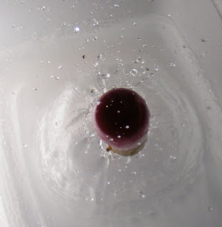
A coloured bulb just hitting the water


Another coloured bulb hitting the water at a diagonal


A really nice splash as the bulb hits the water

Improvements:

As mentioned in the link at the top of the post, a microphone would be an excellent way of doing this, so if anyone has any pointers...

I could also try doing it with a laser, there's an idea.

Any comments/suggestions greatly appreciated.

Chris